| disease | Scoliosis |
Scoliosis is a pathological condition. When one or several segments of the spine exhibit lateral curvature, it can gradually worsen, affecting not only the spine, thorax, ribs, and pelvis, but in severe cases, it may impair cardiopulmonary function and even involve the spinal cord, leading to paralysis. Grade III scoliosis requires surgical correction, while grade I scoliosis can be managed with guided physical therapy, electrical stimulation, traction therapy, and especially brace treatment to prevent or reduce the progression of the deformity.
bubble_chart Etiology
The cause of scoliosis is mostly unknown, and many diseases can lead to lateral curvature of the spine. According to Winter R.B (1983), the causes are summarized as follows:
I. Structural Scoliosis
1. Idiopathic
(1) Infantile (0–3 years)
① Resolving
② Progressive
(2) Juvenile (4–9 years)
(3) Adolescent (10–16 years)
2. Neuromuscular
(1) Neurogenic
① Upper motor neuron
a. Cerebral palsy
b. Spinocerebellar degeneration
Ⅰ. Hereditary ataxia (Friedreich's disease)
Ⅱ. Progressive neurogenic muscular atrophy (Charcot-Marie-Tooth disease)
Ⅲ. Familial ataxia (Roussy-Lévy disease)
c. Syringomyelia
d. Spinal cord tumor
e. Spinal cord injury
f. Others
② Lower motor neuron
a. Poliomyelitis
b. Other viral myelitis
c. Traumatic
d. Spinal muscular atrophy
Ⅰ. Hereditary early-onset spinal muscular atrophy (Werdnig-Hoffmann disease)
Ⅱ. Familial juvenile muscular atrophy (Kugelberg-Welander disease)
e. Myelomeningocele (paralytic)
③ Familial dysautonomia (Riley-Day syndrome)
④ Others
(2) Myogenic
① Multiple arthrogryposis② Muscular dystrophy
a. Pseudohypertrophic muscular dystrophy
b. Limb-girdle muscular dystrophy
d. Facioscapulohumeral muscular dystrophy
③ Fiber type disproportion
④ Congenital hypotonia
⑤ Myotonic dystrophy
⑥ Others
3. Congenital
(1) Formation defects
① Congenital wedge vertebra
② Congenital hemivertebra
(2) Segmentation defects
① Unilateral unsegmented bar
② Bilateral unsegmented bar
③ Mixed type
4. Neurofibromatosis
5. Mesenchymal disorders
(1) Marfan syndrome
(2) Ehlers-Danlos syndrome
(3) Others
6. Rheumatic diseases
7. Traumatic
(1) Fracture
(2) Surgery
① Laminectomy
② Thoracoplasty
(3) Radiation therapy
8. Extra-spinal scar contracture
(1) Post-empyema
(2) Post-burn
9. Osteochondrodystrophy
(1) Diastrophic dwarfism
(2) Mucopolysaccharidosis (e.g., Morquio syndrome)
(3) Spondyloepiphyseal dysplasia
(4) Multiple epiphyseal dysplasia
(5) Others
10. Bone infection
(1) Acute
(2) Chronic
11. Metabolic disorders
(1) Rickets
(2) Osteogenesis imperfecta
(3) Homocystinuria
12. Lumbosacral abnormalities
(1) Spondylolysis and spondylolisthesis
(2) Congenital lumbosacral abnormalities
13. Tumors
(1) Spinal tumors
① Osteoid bone tumor
② Histiocytosis
③ Others
(2) Spinal cord tumors (see neuromuscular type)
II. Non-structural Scoliosis
1. Postural scoliosis
2.Hysterical scoliosis
3. Nerve root irritative scoliosis
(1) Lumbar disc herniation
(2) Tumor
4. Inflammatory stimulation (e.g., appendicitis)
5. Unequal leg length
6. Hip contracture
bubble_chart Pathological Changes
The pathological changes of scoliosis are not limited to the vertebrae. It can involve paravertebral and intervertebral tissues, ribs, the thoracic cage, the spinal canal, and changes in organs such as the heart and lungs. Different disease causes and varying degrees result in distinct pathological changes. Below, the common pathological changes are described as follows:
2. **Rib and Thoracic Cage Changes** With vertebral rotation, the ribs develop a convex-side prominence and a concave-side flattening. The costovertebral angle becomes sharper on the convex side and wider on the concave side. The intercostal spaces widen on the convex side and narrow on the concave side. Due to the rib prominence on the convex side and reduced rib angles, thoracic deformity occurs, narrowing the convex-side thoracic cavity. The ribs themselves often change from flat to triangular in shape.
3. **Intervertebral Disc Changes** The shape of the intervertebral discs wedges in response to vertebral wedging. On the convex side, the disc thickens with increased fibrous ring layers, while on the concave side, the disc thins, and the nucleus pulposus shifts toward the convex side. Although microscopic changes in the disc are minimal, studies report significantly reduced glycosaminoglycan content and increased acid phosphatase activity in scoliotic discs. Additionally, scoliosis can alter the proteoglycan structure of the discs.

5. **Paravertebral Muscle Changes** Patients with scoliosis often exhibit paravertebral muscle atrophy, with greater severity on the concave side. Microscopically, some muscles show degeneration, loss of striations, reduced nuclei, and interstitial fibrosis. Some researchers have observed altered muscle spindle structures in paravertebral muscles, particularly in cases with curvature angles exceeding 50°. Some scholars suggest that idiopathic scoliosis may be myogenic in origin.
6. **Thoracic Organ Changes** These primarily involve functional alterations in the lungs and heart. Scoliosis and vertebral rotation lead to thoracic deformity and respiratory muscle fatigue, restricting lung expansion. Impaired pulmonary function can cause hypoxia, which in turn increases hematocrit, elevates blood viscosity, raises microcirculatory resistance, and increases pulmonary artery pressure, overloading the right heart. In severe cases, this may ultimately lead to cardiopulmonary failure.
bubble_chart Clinical Manifestations
1. History
For first-time patients, a detailed medical history should be obtained. Understand the mother's pregnancy conditions, delivery circumstances, and whether there were any potential teratogenic influences during the first trimester of pregnancy. Inquire whether any siblings or family members have similar conditions or diabetes. Note the age at which scoliosis appeared, the progression of the curvature, whether any treatment was received and the type of treatment. Current primary symptoms should be thoroughly investigated, such as fatigue, shortness of breath or difficulty breathing after exercise, palpitations, numbness in the lower limbs, difficulty walking, and issues with urination or defecation. Grade I scoliosis may present no symptoms, especially in adolescent girls, where the back is often covered, and the deformity may go unnoticed. Therefore, population screening and careful physical examination are key to early detection.
2. Physical Examination
The physical examination includes measuring height, weight, sitting height, and the distance between the middle fingertips with arms extended. The examinee should then expose the entire back, stand naturally with feet shoulder-width apart, eyes level, arms relaxed at the sides, and palms facing inward. Observe whether the shoulders are symmetrical, whether the lower angles of the scapulae are level, whether the waist curves are symmetrical on both sides, whether the iliac crests are of equal height, and whether the spinous process line deviates from the central axis. If more than one of these five items is abnormal, it is classified as trunk asymmetry. Next, perform the Adam's forward bending test: the examinee straightens the knees and slowly bends forward from the neck to the waist, while the examiner observes from the central tangent direction of the back to check whether the upper thoracic, thoracic, thoracolumbar, and lumbar segments are level and symmetrical on both sides. Asymmetry indicates a positive forward bending test, suggesting scoliosis (Figure 1).
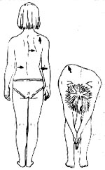
Figure 1 Physical Examination (A) and Adam's Forward Bending Test (B)
During the forward bending test, the examiner may use a scoliosis angle measuring ruler or inclinometer to measure the degree of inclination (or hump angle) in each segment of the back, recording the maximum angle and its location. An asymmetric inclination exceeding 4° suggests scoliosis.
Notes for the physical examination: The physical examination, including the forward bending test, is a fundamental method for scoliosis screening. The forward bending test is recognized as a simple, sensitive, and practical initial screening tool for scoliosis. However, the following points must be noted in practice:
1. The examinee should stand on a flat surface. If there is leg length discrepancy, the shorter limb should be elevated to level the pelvis.
2. The examinee’s back must be fully exposed, and they should be instructed to relax completely.
3. The examinee should face away from the light source, as side lighting may create shadows on the back, leading to false impressions.
4. During the forward bending test, the palms should be pressed together or holding a horizontal rod, allowing the arms to hang naturally, followed by slow forward bending to assess the entire spine.
bubble_chart Auxiliary Examination
1. Moiré Topography
Moiré imaging is an optical method that uses contour lines to represent deformities on the dorsal side of the spine (Figure 1). If a straight line is drawn from the spinous process of C7 to the upper edge of the gluteal cleft as a reference line, a normal Moiré image will show symmetrical wave patterns on both sides of the reference line with equal grid counts. If there is a deformity, differences in height will appear on both sides, resulting in unequal and asymmetrical wave patterns. The more severe the deformity, the greater the height difference and the larger the disparity in wave grid counts. A positive Moiré image is indicated by a difference of one or more grid counts.

Figure 1 Moiré Image
Conventional X-ray examinations cannot reflect the rib and thoracic deformities caused by spinal rotation. Using a specialized grating projection and Moiré imaging device for spinal diagnosis, the different wave patterns produced by varying heights or deformities on the patient's back or waist are captured as Moiré images. During imaging, a ruler is placed on the positioning frame and included in the same image as the patient's back to serve as a measurement scale. For example, a midline is drawn from the C7 spinous process to the gluteal cleft on the image, and the peak points of each wave pattern on the left and right sides are identified from top to bottom. Among these peak points, the two points with the shortest perpendicular distance to the midline and the largest difference in wave grid counts are selected and labeled as a and b (a being the convex side). The height difference between points a and b is H, and the distance between them is (a+b). Based on these markers, the rib hump angle or lumbar hump angle (Hump Angle) can be calculated using a formula, which quantifies the convex deformity of the spine on the dorsal side of the torso (Figure 2). The actual length of a and b is w = (a+b)/scale, and the height difference H between a and b is equal to the difference in wave grid counts × 5 (each wave interval represents a 5mm actual height difference). Thus, the hump angle (HA) = tan-1 H/w. Therefore, Moiré imaging not only provides qualitative but also quantitative significance in assessing scoliosis.
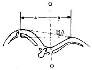
Figure 2 Measurement of Rib Hump Angle
2. Radiological Examination
(1) Conventional X-ray Examination
Like physical examination, it serves as the fundamental basis for the diagnosis and treatment of scoliosis. X-rays help determine the disease cause, type, location, severity, range, and flexibility of the curvature. Depending on the needs, other specialized X-ray examinations may be performed. Radiological examination is used to establish a diagnosis, monitor deformity progression, identify associated deformities, develop treatment plans, or evaluate treatment efficacy.
1. Upright Position Examination
Standing and sitting positions are the basic postures for X-ray examination. Standing images are taken for patients who can stand, while sitting images are used for those with lower limb dysfunction or very young age. The standard posture involves the patient standing with feet together, legs straight, torso erect, and avoiding rotation. For anteroposterior films, the forearms are extended forward at 90° (or placed on a support), and for lateral films, the entire spine should be included in one image whenever possible.
2. Flexibility Examination
After confirming scoliosis with upright films, side-bending films can be taken to assess the flexibility of each curve. The patient lies supine and actively contracts their muscles to maximally bend toward the convex side to correct the deformity. For patients with neuromuscular scoliosis who lack voluntary muscle contraction, a "push-pull method" may sometimes be used during imaging to evaluate flexibility.
3. Traction Imaging
The patient is placed in a supine position, and X-rays are taken with simultaneous upward and downward traction using an occipitomental belt and a pelvic belt. Currently, it is more standard and common to take X-rays under suspension traction, i.e., taking anteroposterior and lateral radiographs under vertical traction with an occipitomental belt (with the patient's feet just off the ground) to assess the flexibility of the scoliosis.
4. Spine Derotation Radiography (Stagnara View)
Structural scoliosis, especially severe cases (over 100°), is often accompanied by spinal rotation. Standard anteroposterior X-rays cannot accurately reflect the true degree of deformity or the actual vertebral malformation in some cases. Therefore, the ideal method involves fluoroscopic visualization, rotating the spine until the scoliotic curve reaches its maximum before taking the radiograph, or rotating until the apical vertebra is in a true anteroposterior position. This approach reveals the true degree of spinal curvature or the actual morphology of the vertebrae.
5. Bone Age Assessment
In scoliosis treatment, the patient's age is a crucial factor. Assessing bone age helps determine whether skeletal growth is ongoing. Girls typically reach skeletal maturity around age 16, while boys mature 1 to 1.5 years later. Therefore, an anteroposterior X-ray of the left hand and wrist is taken to evaluate bone age. The Risser method is commonly used, which involves imaging the iliac crest apophysis to assess skeletal maturity. The length from the anterior superior iliac spine to the posterior superior iliac spine is divided into four segments. Ossification in the anterior quarter is graded as stage 1, the anterior half as stage 2, three-quarters as stage 3, and full length as stage 4. Complete fusion of the apophysis is graded as stage 5, which typically occurs around age 24, making it the last epiphysis to close in the body. At this stage, skeletal growth has ceased, and the scoliotic deformity tends to stabilize. Clear thoracic or lumbar X-rays may also be referenced. Observing the vertebral endplates: if the apophysis appears fragmented, growth is incomplete; if fused, spinal development has concluded.
(2) Tomography
Conventional tomography can provide clearer images of deformities, lesion extent, and nature at specific locations, such as nonunion or pseudarthrosis, which may be unclear on standard radiographs but visible on tomography.
(3) Myelography
For scoliosis, it’s essential to evaluate not only spinal or vertebral deformities but also any coexisting intraspinal anomalies. Myelography is nearly routine for congenital scoliosis to identify concurrent neural abnormalities. Contrast agents like Amipaque or Omnipaque are preferred for their excellent contrast, safety, and minimal side effects. The adult dose is 10–20 ml. Lumbar puncture is typically performed. For ascending studies, a feet-up, head-down position is used; for descending studies, a head-up, feet-down position is employed. However, during head-down positioning, fluoroscopic monitoring prevents contrast from entering the ventricles.
(4) Computed Tomography (CT)
CT scanning offers significant advantages in diagnosing vertebral, spinal cord, and nerve root pathologies, especially in areas poorly visualized on standard radiographs (e.g., occipitocervical or cervicothoracic regions). With a density resolution 20 times higher than conventional X-rays, CT clearly depicts fine structures of vertebrae, the spinal canal, and paravertebral tissues. CT myelography, in particular, provides invaluable insights into the spinal canal’s true condition and the relationship between bony and neural elements, aiding surgical planning.
(5) Magnetic Resonance Imaging (MRI)
MRI is a new, non-invasive multiplanar imaging technique with strong resolution for intraspinal pathologies. It not only identifies lesion location and extent but also distinguishes nature (e.g., edema, compression, hematoma, spinal cord degeneration) better than CT. However, it cannot replace CT or myelography, as each has specific indications.
III. Electrophysiological Examinations
Electrophysiological tests are crucial for detecting coexisting neurological or muscular disorders in scoliosis patients.
(1) Electromyography (EMG)
Electromyography (EMG) utilizes the bioelectrical activity generated during striated muscle contraction, which is detected and amplified through electrodes, displayed on a cathode-ray oscilloscope, and recorded on paper. The analysis is based on individual or collective patterns of muscle potentials to assess the state of motor units and evaluate neuromuscular function. During the examination, the patient lies in a supine position. The skin of the examined area is disinfected, and sterile needle electrodes are inserted into the tested muscles. Observations are made for insertion potentials during needle insertion, resting potentials when the muscle is fully relaxed, and motor unit potentials during muscle contraction. Abnormal EMG findings include fibrillation potentials, positive sharp waves or positive phase potentials, fasciculation potentials, or biphasic potentials.
(II) Nerve Conduction Velocity Measurement
can be divided into motor conduction velocity and sensory conduction velocity. Motor conduction velocity measurement involves using electrical stimulation to record muscle potentials and calculating the speed at which excitation propagates along the motor nerve. Specifically:
Motor nerve conduction velocity (m/s) = distance between two points (mm) / latency difference between the two points (ms).
Sensory nerve conduction velocity measurement involves stimulating a point on the fingers or toes in a forward direction and recording the evoked potential at the proximal end, or stimulating the nerve trunk in a reverse direction and recording the evoked potential at the fingers or toes. The calculation method is the same as above. There are many influencing factors in conduction velocity measurement. For unilateral lesions, it is advisable to use the healthy side as a control.
(III) Evoked Potential Examination
Somatosensory evoked potentials (SEP) have certain practical value in assessing the degree of spinal cord nerve injury, estimating prognosis, or observing treatment effects. In recent years, we have used direct placement of stimulation and recording electrodes in the subarachnoid space or epidural space to record spinal cord evoked potentials (SCEP) during spinal surgery, enabling segmental monitoring of the spinal cord. The waveforms are stable and clear, unaffected by anesthesia or drugs, providing a reliable monitoring tool for spinal surgery.
IV. Pulmonary Function Testing
Due to vertebral rotation, scoliosis can cause thoracic deformity and respiratory muscle fatigue, while also restricting lung expansion. Therefore, scoliosis is often accompanied by pulmonary dysfunction, with severity increasing as the curvature worsens. Based on preoperative pulmonary function tests in 105 scoliosis patients, all but two cases exhibited varying degrees of pulmonary dysfunction, with 16% having vital capacity below 50% and 30% having forced expiratory vital capacity below 50%. Normal thoracic or back surgery can reduce vital capacity by 10–15% due to postoperative pain. Thus, patients with severe spinal deformities and vital capacity below 40% should undergo pulmonary function expansion exercises before spinal corrective surgery.
V. X-ray Measurement of Scoliosis
(I) Measurement of Scoliosis Angle
1. Cobb Method: On an anteroposterior X-ray, first identify the upper and lower end vertebrae of the scoliosis. The vertebra with the greatest inclination of the endplates toward the concave side at the upper end of the main curve is the upper end vertebra, and the one at the lower end is the lower end vertebra. Draw a horizontal line along the upper edge of the upper end vertebra and the lower edge of the lower end vertebra. Perpendicular lines are then drawn to these two horizontal lines, and the angle formed by their intersection is the Cobb angle, which can be measured with a protractor.
2. Ferguson Method: On an anteroposterior X-ray, draw a line from the center of the upper end vertebra to the center of the apical vertebra, and another line from the center of the lower end vertebra to the center of the apical vertebra. The supplementary angle formed by these two lines is the Ferguson angle.
Of these two methods, the Cobb method is more commonly used and is almost universally standardized. However, it is important to note that in diagnosis, treatment, and follow-up, the same end vertebrae should be used for measurement in the same patient to ensure consistency and comparability.
(II) Measurement of Vertebral Rotation
In structural scoliosis, vertebral rotation is often present. Methods for measuring rotation include:
1. Using the spinous process as a marker: On an anteroposterior X-ray, the spinous process is normally centered in the vertebral body. If the midline of the vertebral body to its lateral edge is divided into three equal parts, rotation causes the spinous process to shift toward the concave side. A shift of one part is Grade I, two parts is Grade II, three parts is Grade III, and beyond the vertebral edge is Grade IV (Figure 3).
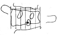
Figure 3: Measurement of Vertebral Rotation (Spinous Process Method)
If the deviation of the apical vertebra's spinous process from the midline is converted into degrees: a deviation of 1/3 of half the vertebral body equals 15°, 2/3 equals 30°, and projection at the vertebral edge equals 45°.
2. Using the pedicle as a landmark (Moe's method) On the anteroposterior X-ray film, observe the positions of bilateral pedicles and similarly divide half of the vertebral body into three equal parts. Normally, the pedicles are symmetrical and located in the outer 1/3. If the vertebral body rotates: - Pedicle located in the middle 1/3 indicates Grade I rotation, - Pedicle located in the inner 1/3 indicates Grade II rotation, - Pedicle located at the midline indicates Grade III rotation, - Pedicle rotated beyond the midline to the opposite side indicates Grade IV rotation (Figure 4).
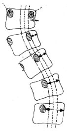
Figure 4 Vertebral Rotation Measurement (Moe Method)
Based on the author's quantitative measurement of rotation in 328 vertebrae from scoliosis patients and normal individuals, compared with the corresponding Nash-Moe rotation grades on X-rays. Specifically, Nash-Moe Grade I rotation corresponds to an actual vertebral rotation angle of 10.42±2.14 degrees, Grade II to 24.03±3.91 degrees, Grade III to 32.94±4.51 degrees, and Grade IV to over 50 degrees.
3. Measurement of Vertebral Wedging As scoliosis progresses, vertebral height becomes unequal on both sides, resulting in wedging, where the concave side of the vertebra shows reduced height. If the vertebral height on a normal anteroposterior X-ray is divided into 4 grades, a height reduction of 0–1/6 on one side is Grade I, 1/6–1/3 is Grade II, 1/3–1/2 is Grade III, and over 1/2 is Grade IV.
All examinations should be properly documented for follow-up applications.
bubble_chart Treatment Measures
The treatment of scoliosis can be divided into two main categories: non-surgical treatment and surgical treatment. Early cases are mostly treated with non-surgical methods, including: exercise therapy, electrical stimulation therapy, traction therapy, plaster orthosis treatment, and brace treatment. However, for idiopathic scoliosis with rapid progression during adolescence, a Cobb angle exceeding 40°, or rigid congenital scoliosis unresponsive to non-surgical treatment, early surgical intervention is recommended. Below, we focus on introducing non-surgical treatment and commonly used surgical treatments:
I. Non-surgical Treatment
(1) Corrective Exercise Therapy
The efficacy of corrective exercises for scoliosis remains controversial. However, based on the author’s results in treating idiopathic scoliosis with a curvature under 20° using corrective exercises, the regression rate in the treatment group was 29.6%, significantly higher than that of the untreated observation group. The principle of corrective exercises is to selectively strengthen the muscles that maintain spinal posture. By targeting the sacrospinalis, abdominal muscles, psoas major, and quadratus lumborum on the convex side, muscle balance between the two sides can be adjusted. Additionally, it stretches the contracted muscles, ligaments, and other soft tissues on the concave side to achieve corrective effects. Corrective exercises yield varying results depending on the developmental stage and type of scoliosis. They are particularly effective for children or prepubescent patients with grade I idiopathic scoliosis, where flexibility is good and no significant structural changes have occurred. In such cases, exercise therapy can achieve favorable outcomes. However, for cases with obvious structural changes or congenital scoliosis, corrective exercises alone are insufficient and must be combined with other non-surgical treatments, especially brace therapy. Therefore, exercise therapy remains a necessary auxiliary treatment to prevent muscle atrophy and other disuse-related changes caused by immobilization. Below is a set of corrective exercises developed by the author. Depending on the patient’s condition, specific sections can be emphasized. The full set consists of nine exercises:
1. Forward and Backward Crawling The patient assumes an elbow-knee position and crawls forward and backward using the elbows and knees (Figure 1).
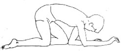
Figure 1: Forward and Backward Crawling
2. Side Sitting The patient kneels with hands raised overhead, first sitting to the right side (a), then to the left side (b, c), alternating repeatedly (Figure 2).
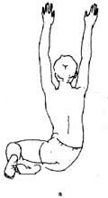
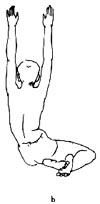
 Figure 2: Side Sitting
3. Touching the Wall with the Head The patient lies prone, face down, with shoulders abducted and elbows flexed, hands extended forward. The head is stretched forward as far as possible to touch the wall with the crown, then retracted, and repeated (Figure 3).
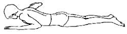
Figure 3: Touching the Wall with the Head
4. Arm Extension The patient lies prone with hands resting on the forehead. The arms are gradually lifted off the ground, extended forward, and then returned to the forehead, repeating the motion (Figure 4).
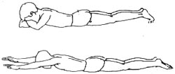
Figure 4: Arm Extension
5. Sit-ups The patient lies supine with arms extended overhead on the mat. Then, they perform a sit-up, bending the torso forward, extending the arms to touch the toes, and slowly returning to the supine position with arms raised (Figure 5).
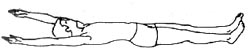

Figure 5 Sit-ups
6. Lower Limb Extension The patient lies prone, with shoulders abducted, elbows slightly flexed, and palms flat on the mat. The lower limbs are extended backward and lifted off the mat, performing alternating scissor-like movements with the left and right legs (Figure 6).
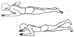
Figure 6 Lower Limb Extension
7. Leg Raises The patient lies supine, hands under the head, lower limbs slightly flexed, and feet flat on the mat. Then, the legs are raised, performing alternating scissor-like movements (Figure 7).

Figure 7 Leg Raises
8. Deep Inhalation and Slow Exhalation The patient lies supine, upper limbs placed flat on the sides with palms up, lower limbs slightly flexed, and feet flat on the mat. Deep inhalation is performed through the nostrils to expand the chest, followed by a gentle exhale through the mouth (Figure 8).
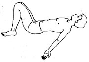
Figure 8 Deep Inhalation and Slow Exhalation
9. Upright Standing The patient stands with feet parallel and close to a wall, ensuring the shoulders and hips are pressed against the wall, while the head, neck, and spine are stretched upward as much as possible (Figure 9).
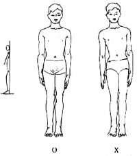
Figure 9 Upright Standing
(2) Electrical Stimulation Therapy
Bracing is an effective method to control the progression of scoliosis. However, due to its restrictions on daily activities, bulky appearance, and poor breathability—especially in hot climates—patients or caregivers often discontinue treatment prematurely and prefer electrical stimulation therapy. Currently, dual-channel surface electrical stimulators are commonly used. Two sets of electrodes are placed at specific positions on the convex side of the curvature, delivering alternating rectangular stimulation waves to induce rhythmic contraction and relaxation of the paraspinal muscles, thereby applying continuous corrective force to the spine to prevent further progression. This method is particularly suitable for younger patients with flexible idiopathic scoliosis under 40° or neuromuscular scoliosis. Specific treatment methods include:
1. Positioning Before treatment, a standing anteroposterior spinal X-ray is taken to identify the apex vertebra and its corresponding rib. Points A and B, where this rib intersects the posterior and mid-axillary lines, serve as reference centers. Electrodes are placed 5–6 cm above and below these reference points along the posterior and mid-axillary lines, ensuring a minimum distance of 10 cm between electrodes in the same set.
2. Determining Effective Intensity Sufficient stimulation intensity is required for therapeutic efficacy. The appropriate intensity can be estimated by: ① Observing visible improvement or straightening of the scoliosis during muscle contraction. ② Palpating the spinous processes for movement during muscle contraction. ③ Comparing X-rays with and without stimulation to assess whether the curvature angle decreases by at least 10°. If these criteria are not met, adjust the electrode positions forward or backward, or slightly increase the distance between electrodes in the same set to find the optimal stimulation point, gradually increasing the current intensity to 60–70 mA.
3. Treatment Prescription First Week: - Day 1: Stimulation for half an hour, twice daily. - Day 2: Stimulation for 1 hour, twice daily. - Day 3: Stimulation for 3 hours, once daily. - Thereafter, increase by 1 hour each day, once daily, reaching 7 hours by Day 7. The current intensity should increase from 30mA on Day 1 to 70mA by Day 7. After one week of daytime treatment to help the child gradually adapt, parents should be taught how to correctly use the electrical stimulator and place the electrode pads. Subsequently, the treatment should be shifted to nighttime. After the child falls asleep, start the device with a current intensity of 30mA, then gradually increase it to 60–70mA over a few minutes to avoid overly strong stimulation that might wake the child.
During the initial treatment phase, be alert for the occurrence of rashes. Frequently verify the stimulation points to prevent insufficient stimulation intensity or duration. Electrical stimulation therapy requires persistence. To achieve optimal therapeutic effects, it can also be combined with orthotic treatment.
(3) Orthotic Therapy
Orthotic therapy plays a crucial role in the non-surgical treatment of scoliosis. Winter et al. treated 95 cases of idiopathic scoliosis with Cobb angles between 30–39° using the Milwaukee brace, discontinuing use after skeletal maturity. After a follow-up period of two and a half years, 84% of the curves remained unchanged or improved. The authors treated 215 idiopathic scoliosis patients with an average Cobb angle of 28°—using the Milwaukee brace for cervicothoracic and thoracic curves and the Boston brace for thoracolumbar and lumbar curves. After an average follow-up of 26 months, the efficacy rate (unchanged or improved curvature) was 82%. Orthotic therapy is suitable for idiopathic scoliosis in juveniles and adolescents but ineffective for congenital scoliosis or scoliosis in skeletally mature individuals. Commonly used braces for scoliosis fall into two main categories: CTLSO and TLSO.
1. CTLSO The fixation range includes the cervical, thoracic, lumbar, and sacral vertebrae. The Milwaukee brace is representative, featuring a plastic pelvic section with three uprights (one anterior and two posterior). These uprights connect to a neck ring at the top, which has an occipital pad at the back and an anterior mandibular pad pressing against the throat. CTLSO is suitable for curves with an apex at or above T8. Pressure pads or slings can be added to the uprights as needed, with the main pad placed at the level of the curve’s apex. The pad should be positioned as laterally as possible to increase the horizontal corrective force.
2. TLSO The fixation range includes the mid-to-lower thoracic, lumbar, and sacral vertebrae. The Boston brace is a typical example. TLSO is suitable for curves with an apex below T8. Made of plastic, this brace extends from the axilla down to the pelvis and can be concealed under clothing, making it more cosmetically acceptable. However, such braces require a gypsum mold, sometimes taken under traction or with pressure pads, to create a negative cast, which is then used to form a positive mold. The plastic brace is fabricated over this mold to ensure optimal corrective effects.
3. Duration of Brace Wear The brace should be worn for no less than 23 hours daily, with 1 hour reserved for bathing, exercises, and other activities. Orthotic therapy requires long-term commitment and should continue until skeletal maturity unless contraindicated. Criteria for discontinuing brace use: ① No height increase over 4 months. ② Risser sign grade 4–5 (complete ossification and fusion of the iliac crest apophysis). After removing the brace for 4 hours, a radiograph should show no change in the Cobb angle. If these criteria are met, brace wear can be reduced to 20 hours daily. If no change is observed after 4 months, reduce to 16 hours. If stability persists, further reduce to 12 hours. After another 3 months, if a standing AP radiograph taken 24 hours after brace removal shows no change in the Cobb angle, discontinue use. If deformity worsens during this period, resume full-time brace wear (23 hours daily).
(4) Traction Therapy
Traction therapy can prevent or slow the progression of scoliosis or achieve some degree of correction. Currently, its primary role is as preoperative preparation for scoliosis surgery, enabling maximal intraoperative correction while avoiding sudden, excessive spinal distraction that could lead to spinal cord or nerve injury complications. Various traction methods exist, such as cervical traction, inclined table cervical traction, cervical-pelvic traction, halo-pelvic traction, and supine reverse suspension traction. The latter two are described below:
1. Halo-Pelvic Traction This device was first designed and applied clinically by Dewald and Ray in 1970. It consists of a halo ring, a pelvic ring, and four support rods. The halo ring is fixed to the skull with specialized screws, while the pelvic ring can be secured with Steinmann pins, specialized screws, a pelvic belt, or a gypsum cast around the waist.
(1) Halo Installation The patient's hair is shaved, and they lie supine with their head supported and fixed beyond the edge of the bed by an assistant. The skin is routinely disinfected, and the procedure is performed under local anesthesia. The halo should be placed below the maximum circumference of the skull, approximately 1 cm above the eyebrow arch and the tip of the ear. The distance between the halo and the scalp should be 1–1.5 cm. The halo is connected and fixed to the skull using four specialized cranial screws. The two anterior screws are inserted through the skin 1 cm above the outer third of the eyebrow arch, while the two posterior screws are diagonally opposite the anterior screws and tightened until a torque of approximately 6 kg is achieved (when three fingers can no longer turn them). The screws are tightened into the outer table of the skull.
(2) Pelvic Ring Installation After general or local anesthesia, the patient is placed in a lateral position with the surgical side up. An assistant places a Steinmann pin at the posterior superior iliac spine as a guide. The surgeon then inserts another Steinmann pin from 0.5 cm below the anterior superior iliac spine toward the guide pin, with the ideal exit point at the center of the posterior superior iliac spine. Once one side is completed, the patient is turned to perform the procedure on the opposite side. The Steinmann pin method is challenging and carries many complications. Currently, the screw fixation method is more commonly used: the patient lies supine on an orthopedic surgical table with the pelvis suspended. An assistant holds the pelvic ring while two surgeons simultaneously insert three specialized screws on each side, starting 0.5 cm below the anterior superior iliac spine and spaced 1.5–2.0 cm apart from front to back, until the pelvic ring is securely fixed.
No traction is applied for the first 2–3 days postoperatively. Once the pain subsides, the support rods are installed. For the first three days postoperatively, the fixation screws should be tightened daily, and the adjustment screws should be turned 1–2 turns per day until the desired correction is achieved.
2. Reverse Suspension Traction for Scoliosis This device consists of traction straps, pulleys, ropes, and weights. The patient lies on their side in the traction straps with the convex side of the curvature facing downward. The weight is gradually increased from 10 kg to 40 kg until the apex of the convex side is 5–8 cm off the bed, limited by the patient's maximum tolerance. If used solely for preoperative preparation, the traction period is generally around two weeks. Traction helps loosen the soft tissues on the concave side and effectively stretches the spinal concave side. This method is simple, convenient, has few complications, is mechanically sound, and yields reliable results. Patients can freely enter and exit the traction device without requiring special care. It can be applied in hospitals, at home, or in seasonal disease wards.
II. Surgical Treatment
(1) Surgical Indications
1. Disease Cause Idiopathic scoliosis with rapid progression during adolescence and a Cobb angle greater than 40° should be treated surgically. Congenital scoliosis, especially the rigid type, or neuromuscular scoliosis causing spinal collapse, should be treated early. The longer the condition persists, the more severe it becomes and the harder it is to correct.
2. Age Generally, instrumented correction, fixation, and fusion surgery are performed after the age of 12. For congenital scoliosis, early surgery is recommended to prevent progression through localized fusion.
3. Degree of Scoliosis Currently, the general standard domestically and internationally is surgical treatment for Cobb angles greater than 40°, while non-surgical treatment is used for angles below 40°.
4. Location of Scoliosis Thoracic scoliosis with severe rotation, significant thoracic deformity, or a large hump angle should be operated on earlier than lumbar scoliosis to prevent worsening respiratory function.
5. Scoliosis with Early Paraplegia Patients with early paraplegia should undergo early surgery to decompress and remove the factors causing paraplegia, correct the deformity, and prevent further progression.
6. Adult Scoliosis For older adults with scoliosis, spinal fusion may be considered if they experience back pain due to vertebral osteophyte formation at the deformity site or spinal instability.
(2) Common Surgical Procedures
1. Harrington Surgery Harrington first reported in 1962 the use of a metal internal fixation device to support or apply pressure to correct scoliosis deformities. The device mainly consists of two parts: a rod and a hook. A distraction rod is placed on the concave side of the curve, while a compression rod is placed on the convex side. The proximal segment of the distraction rod is ratcheted to allow only distraction and no reversal when placed in the hook. Its distal end is square-shaped to prevent rotation after insertion into the lower hook. The compression rod is thinner, more flexible, and threaded along its entire length. The upper hook of the distraction rod has a round hole, while the distal hook has a square hole. The Rochester-type compression rod features a groove on the back of the hook, making it easier to insert the compression rod and washers. The upper hook of the distraction rod is typically placed between the facet joints of the thoracic vertebrae, while the lower hook is placed on the upper edge of the lumbar lamina. The upper hook of the compression rod is placed at the costotransverse joint, and the lower hook is placed on the lower edge of the lumbar lamina. The Harrington instrumentation provides good longitudinal support but is less effective for Cobb angles greater than 50°. Smaller angles result in weaker corrective forces, while excessively large angles may require the use of two distraction rods or a combination of distraction and compression rods.
The Harrington surgical procedure has now been internationally standardized. After general anesthesia, the patient is placed in a prone position on the Hall-Relton surgical frame. The skin is sterilized, and a sterile membrane is applied. Before making the skin incision, a 1:400,000 epinephrine solution is injected subcutaneously and into the muscles to reduce bleeding. A straight incision is made over the spinous processes of the vertebrae above and below the intended fusion segment. The soft tissues over the spinous processes and laminae on both sides are stripped subperiosteally until the facet joints or costotransverse joints are exposed. A self-retaining retractor is used to spread the muscles on both sides. On the concave side of the scoliosis, the facet joint above the upper end vertebra is identified, incised, and the upper hook is placed. The lower hook is placed on the upper edge of the lamina of the vertebra below the lower end vertebra. A spacer hook is placed above each of the upper and lower hooks. The spinal external fixation distractor is placed between the two spacer hooks. The distractor knob is rotated to distract the scoliosis from the concave side. A distraction rod of appropriate length is selected and threaded through the holes of the upper and lower hooks. The external distractor is removed, and a hook distractor is used to further distract the upper hook by 1-2 notches on the serrated steps of the upper segment of the distraction rod to achieve maximal correction. An intraoperative wake-up test or evoked potential monitoring is then performed to confirm no overcorrection. The spinous processes, laminae, and facet joints of the intended fusion segment are decorticated to prepare the graft bed. Autologous iliac bone graft or a combination with allograft is then used for fusion. Before wound closure, 1-2 negative pressure drainage tubes are placed to reduce hematoma and prevent infection.
When the Harrington distraction rod is used in combination with a compression rod, the compression rod should be placed first. Currently, Harrington distraction instrumentation is often combined with Luque segmental sublaminar wire fixation to reduce complications such as hook dislodgment and rod breakage associated with the Harrington procedure alone.
2. Luque Procedure First reported by Luque from Mexico in 1976. Two "L"-shaped metal rods are placed on either side of the laminae of the scoliotic segment. The short arm of one rod is inserted into the spinous process above the upper end vertebra of the scoliosis, while the short arm of the other "L"-shaped rod is inserted into the spinous process below the lower end vertebra of the scoliosis. This arrangement forms a rectangular frame, preventing the rods from sliding or rotating. All interspinous ligaments and ligamentum flavum within the intended fixation segment are removed, and the interlaminar spaces are opened. Wires are passed through each interlaminar space, beneath the lamina, and out through the adjacent interlaminar space. The sublaminar wires at each segment are tightened around the metal rods on each side, securing the laminae firmly to the rods.
Luque Procedure Steps: Positioning, incision, and exposure are the same as in the Harrington procedure. After exposure, the following steps are performed:
1) Laminar Fenestration After removing the interspinous ligaments or part of the spinous processes, the ligamentum flavum is exposed. A small hole is first made with a rongeur, and a nerve dissector is inserted to separate the epidural space. A small-angled Kerrison laminectomy rongeur is then inserted into the epidural space, gently compressing the epidural fat, and the ligamentum flavum is lifted and removed. A 0.5 cm diameter fenestration is created in the interlaminar space to allow wire passage.
2) Sublaminar Wire Passage A soft, non-elastic wire with a diameter of 0.8–1.0 mm is cut to about 50 cm in length and folded into a double strand, leaving a small circular loop at the tip. The tip of the double-strand wire is bent into an arc with a diameter equal to the distance between the two laminar fenestrations. The arched tip of the wire is inserted into the lower interlaminar fenestration, passed through the epidural space, closely following the undersurface of the lamina, and exits through the upper interlaminar fenestration. A small hook is used to grasp the loop at the wire tip, pulling the wire snugly against the lamina. The tip of the double-strand wire is then cut to separate it into single strands, which are spread to the left and right sides for fixation to the "L"-shaped rods.
3) Fixing the "L"-shaped rod Generally, the "L"-shaped rod is first placed on the concave side. A wire is looped around the metal rod, then the wires are crossed and twisted tightly. The ligation is performed one by one from top to bottom. During the wire twisting process, the assistant can gently push the convex side to facilitate correction. Then, another "L"-shaped rod is placed on the convex side, and each wire passing under the lamina is ligated one by one from top to bottom using the same method. This allows the two "L"-shaped rods to use the apex vertebra of the scoliosis as a fulcrum, functioning like a "splint" to correct the scoliosis.
Bone grafting and fusion are similar to the Harrington procedure. The Luque procedure provides strong fixation and has a low postoperative pseudarthrosis rate, but each wire passes through the epidural space, increasing the risk of spinal cord injury.
3. Harri-Luque Spinous Process Base Bone Button Wire Fixation Method Since 1985, the author has used a combination of Harrington and Luque instrumentation, but instead of sublaminar wire fixation, two parallel 1.5mm diameter holes are drilled horizontally through the thickest part of the spinous process base using a punch parallel to the lamina. Pre-prepared bone-button wires are threaded through these holes from one side to the other, and the ends of the wires are used to fix the Harrington or Luque rod on that side. This method changes the transverse pulling force on the spinous process (as in the Wisconsin method) into opposing compressive forces of equal magnitude and opposite direction (Figure 10), significantly enhancing the wire's fixation strength.
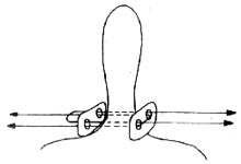
Figure 10 Schematic Diagram of Spinous Process Base Bone Button Wire Fixation
Biomechanical testing and clinical comparison in over 100 cases have demonstrated that this method achieves comparable correction rates and fixation strength to the Luque method. However, it reduces the complexity of sublaminar wire passage in the Luque method and minimizes or eliminates the risk of direct spinal cord and nerve injury.
4. Dwyer Procedure In 1969, Australia's Dwyer introduced an anterior approach for correcting scoliosis. This procedure is primarily suitable for scoliosis deformities below L1, especially in cases with severe laminar defects or deformities where hooks cannot be placed. The surgery typically involves a thoracoabdominal incision on the convex side, resecting the 10th rib to enter the thoracic cavity, and exposing the anterolateral aspect of T11 to L5 extraperitoneally. The segmental vessels crossing the vertebral bodies are ligated. The anterior longitudinal ligament and periosteum are incised longitudinally and stripped laterally to expose the vertebral bodies. The intervertebral discs within the scoliotic segment are excised, and a perforated screw is inserted into each vertebral body. A cable is threaded through the screws and tightened to approximate the vertebral bodies, eliminating the convex-side intervertebral gaps and straightening the spine. The screws are crimped to prevent cable slippage, achieving scoliosis correction. Although this method provides satisfactory correction, it has a high complication rate.
5. Zielke Procedure The Zielke device is essentially a modified Dwyer instrument, also employing an anterior approach. Its greatest advantages are superior correction, derotation capability, and fewer fixed segments. It applies only compression, not distraction, to the deformed segments, reducing the risk of nerve traction injury.
6. C.D. (Cotrel-Dubousset) Procedure In 1984, France's Cotrel and Dubousset reported their new scoliosis correction and fixation system. It is primarily indicated for adolescent idiopathic scoliosis and remains one of the most effective posterior spinal correction systems. However, the technique is complex and carries a relatively high complication rate.